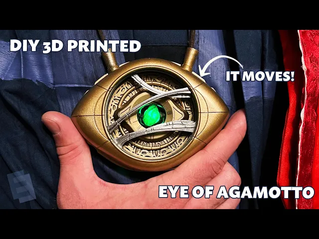
Eye Of Agamotto 2.0
Wearable Eye Of Agamotto
Intro
This project was born after seeing someone else’s better version of my first Eye of Agamotto prop. Determined to improve, I designed a smaller, more accurate version with four independently rotating rings powered by a single motor and a clever geartrain. Extensive test printing, a custom circuit board, and careful power optimization made it one of the most challenging builds I’ve tackled. The result? A compact, mesmerizing prop that feels like magic—assuming you can troubleshoot the occasional grain of sand ruining everything. Version 3 might streamline the design, but for now, this one gets the job done (and looks great doing it).
Concept Origin
This project began as a response to being nerd-sniped by someone else’s work. After releasing my first Eye of Agamotto prop, I was feeling pretty good about it until another version that was undeniably better was released a week later. Their design was smaller, more accurate to the movie, and featured four independently rotating rings. That pushed me to try again.
In the movie, the rings of the Eye of Agamotto move in ways that defy physical reality—they self-intersect and rotate in directions that aren't physically possible. My first design simplified this by grouping the four rings into two pairs, each moving in opposite directions. It worked, but was a compromise. For this second version, I aimed to create four independent rings, each moving at different speeds, while also making the prop smaller and truer to the movie’s scale. On top of that, I wanted to achieve this mechanically, without relying on multiple motors. The challenge was part of the appeal.
The other creator’s design used four motors to drive the rings, but I wanted to see if I could achieve the same effect with a single motor and a clever geartrain. It was ambitious, but that’s what made it exciting.
Design & Development
Making the prop both smaller and more complex isn’t the typical progression for a project like this. From the start, I knew the solution would require minimizing friction and finding a small but powerful motor. My first design used a simple servo, but this time I opted for an N20 motor to handle the increased complexity.
Determining the gear ratios was a critical part of the process. It’s hard to summarize the steps in a short write-up, but the general approach involved imagining the desired motion, translating that into CAD, and iterating until the mechanism worked. One major lesson from the first design was the importance of keeping the power path as direct as possible. In that version, the motor drove the geartrain from one side of the mechanism, and the power had to travel through several gears before reaching the rings. That inefficiency made the whole thing harder to rotate. For this design, I placed the motor so it almost directly powered the rings, which was especially important since there were now four of them instead of two.
The mechanism for opening the Eye (with a slight delay) remained largely unchanged from the first version. It worked well, so I didn’t see a need to reinvent it. However, one major improvement was separating the mechanical components from the aesthetic ones. Gears often need lubrication to work smoothly, but lubricated parts are nearly impossible to paint. To address this, I designed the internal mechanism to handle all the geartrain and motion, while the outer shell could be painted and finished without interference from grease.
Prototype & Build
This project involved extensive test printing. I spent a significant amount of time tweaking individual parts of the assembly before committing to a final build. Experience from the first design helped streamline the process, and by isolating specific problem areas, I was able to keep the number of full prototypes relatively low. The smaller size of this version did make print tolerances more critical, but hobby-grade 3D printers had improved significantly in the years since my first build, which made the process smoother.
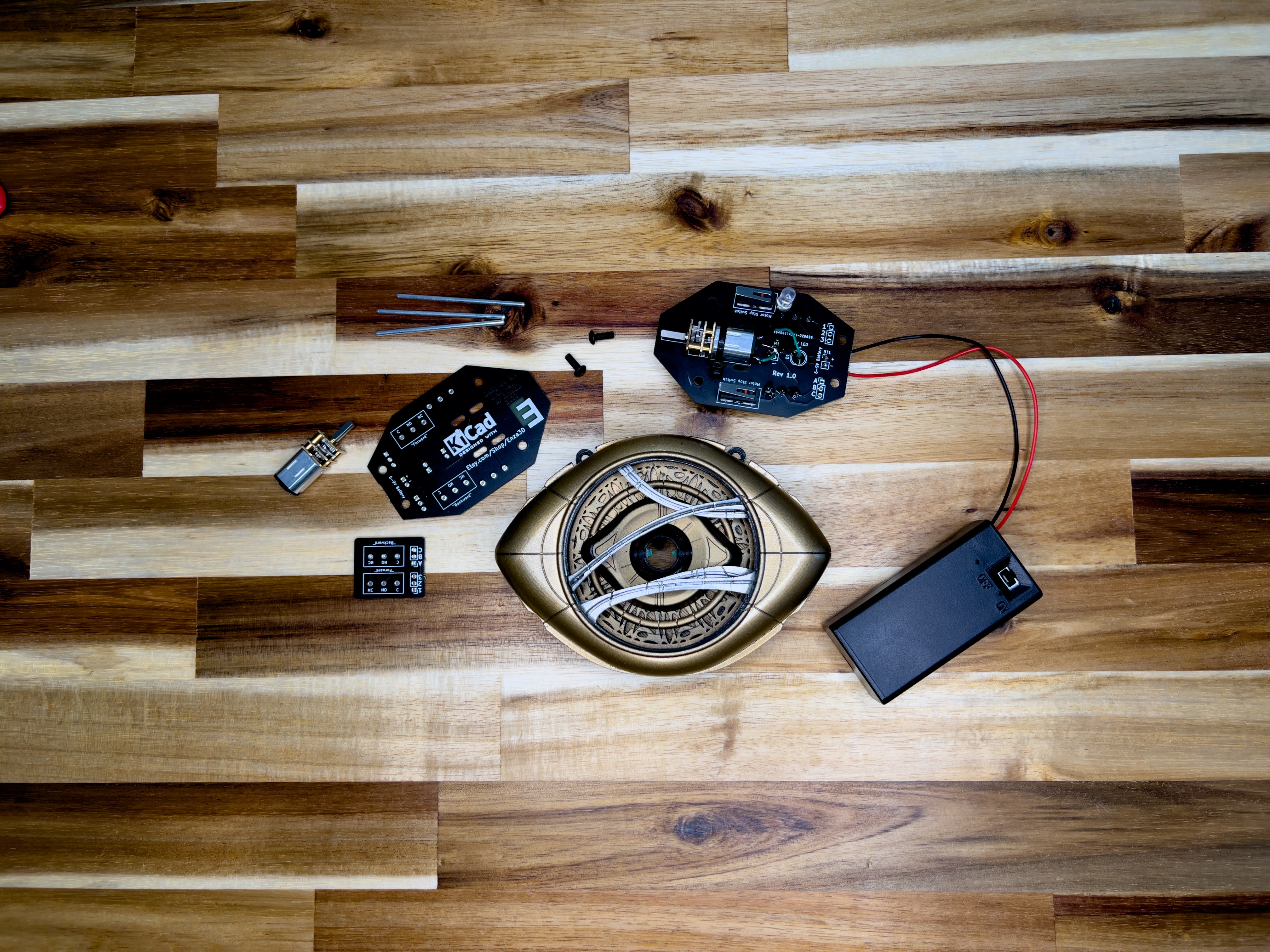
One major addition to this version was a custom circuit board. The first design used a servo, which made controlling the motor position straightforward. With the N20 motor, I needed to add limit stops to prevent over-rotation. I also wanted the prop to be battery-powered, which meant managing more than 10 connections. Wrangling all those wires would’ve been messy, so I collapsed everything into a single, thin circuit board. This was my first time designing a PCB, and it turned out to be a great beginner project—essentially a compressed stack of wires. It worked beautifully and made the final assembly much cleaner.
Final Result
The final design is one of the most challenging things I’ve ever made, but it’s also one of the most satisfying. The smaller size makes it feel more like magic when you see it in action, and the independent motion of the rings is mesmerizing.
This isn’t a beginner-friendly build, though. The assembly is designed to go together fairly easily, but troubleshooting can be tricky. A single grain of sand in the wrong place can make the entire mechanism look broken. For someone with the skills to identify and fix those tiny issues, the result is worth the effort.
I have plans for a Version 3 someday—something easier to assemble and closer to a turnkey solution. For now, though, this version is a reminder of why I love projects like this: the challenge, the learning, and the joy of creating something that feels like magic.